How Valves Work.
Sound
Lasers
Video.
Tech Tips
A guide to the working of vacuum tubes and valves
The Diode Valve
The valve consists of two main parts: a heated cathode which emits electrons and an anode which collects the electrons emitted by the hot cathode. Electrons are fundamental particles that carry an electric current. They have a negative charge and as such will be attracted to a positive charge. If we now put a positive charge on the anode then the electrons will flow from the hot negative cathode to the positive anode.
 Metals do not emit electrons easily and are coated with thoriated tungsten or other substances, which gives off electrons easier. The metal cathode needs to be heated to give off electrons. If the high voltage supply for the anode is switched on before the heater is hot, the anode will strip the cathodes coating of thoriated tungsten off.
This is known as stripping the cathode and reduces the valve's efficiency. This is why some amplifier companies fit a standby switch, which switches the heaters on. The fitting of a standby switch is a reasonable upgrade to have done to your valve amplifier, but get it done by a proper repair company. This upgrade is safety critical and must be done correctly or not at all.
Cathode Space Charge
When the metal cathode is heated it will give off electrons, and a cloud of electrons will coalesce surrounding the cathode. As electrons they will have a negative charge and they form what is called a space charge around the cathode. This space charge being composed of electrons is negative so that it will repel negative charged particles back towards the cathode limiting any current flow. If the anode of the valve is now made positive with respect to the cathode, the anode will attract the negative space charge and electrons will flow from cathode to anode. This flow of electrons is called current and is measured in amps given the symbol I. It can be seen from this that electrons can only flow in one direction, from cathode to anode, which is the reason it is called a valve. It is also called a vacuum tube.
The valve needs a vacuum as the atoms in the air will be hit by the electron stream and absorb energy and heat the valve. At high voltages and high current the electron stream can rip apart the atoms of the gases and cause the gas to glow, in the same way as a neon tube or gas laser like the helium neon or argon ion lasers. The colour of the glow depends on the gases in the valve.
One can often see the valves in music amps glow. This is an early warning sign that there is something wrong with your output valves or your output transformer is failing. I am not talking about the red glow that comes from the valve heaters but an eerie flash as the guitarist plays a loud chord; this is called flashover. If this happens get the amp serviced. If you do not, you will blow your output valves, the output transformer. and possibly your speaker.
The Triode Valve
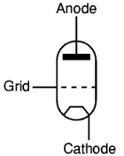
The triode valve has as the name suggests three parts. The extra component is called the grid or control grid. And as the name suggests the grid controls the electron current flowing through the  valve.
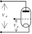
Just as the space charge can limit the current emitted by the cathode. We can limit the current by adding a third electrode around the cathode. We can then vary the voltages on this grid and control the flow of electrons from cathode to anode. Making the grid more negative repels electrons reducing anode current. Making it positive attracts electrons from the cathode allowing a grid current to flow. This is not good as you lose control of anode current and you will burn out your grid.
As we mentioned earlier the electron has a negative charge so it is attracted towards a positive charge and repelled by a negative charge. So if the grid is negative with respect to the cathode it will repel the electrons stopping them from reaching the anode. If the grid is made positive with respect to the cathode then electrons will be attracted to the grid. When the electrons reach the grid the electrons are attracted by the more positive anode and the electrons flow to the anode.
The grid can now be used to control the current through the valve. A small voltage change on the grid will produce a large voltage change on the anode. The ratio between the two is the gain or amplification of the valve. If the grid becomes too positive with respect to the cathode the grid will attract too many electrons and a grid current will flow. This grid current will burn out the valve. Luckily, the only way for this to happen is if you lose your anode load or blow your output transformer.
Never run a valve amplifier without a load such as a speaker. You could blow your output valves.
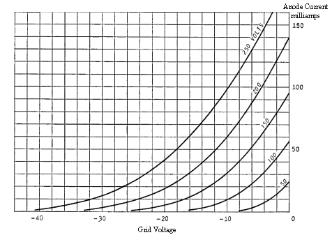
The graph below plots the anode current against the grid voltage for different values of anode voltage. You will notice that the graph does not extend beyond 0V to a positive voltage as at this point there is a chance of grid current flow and thus valve damage. The valve is designed so that it requires a large negative voltage to fully block the flow of electrons from cathode to anode. The graph also shows that anode current is affected by anode voltage as well as grid voltage. The higher the positive voltage on the anode with respect to the cathode, the more current will flow in the anode.
Triode Transfer Characteristics

The transfer characteristic or mutual conduction curve is the first measurement that is made on the valve. This is the value of anode current for different values of grid voltage. Mutual conductance is abbreviated to the letters gm. Sometimes it is called transconductance. On early valve data sheets the mutual conductance value was often followed by the letter S. This is not the symbol for mutual conductance, it is an abbreviation of the term Siemen which is a unit of electrical conductance in the International System. It is equal to one ampere per volt. This is alternatively measured in units of Mhos,. This is a play on the name of the scientists Ohm (famous for his definition of the ohm) as mho is ohm backwards. Conductance is amps divided by volts. Resistance is volts divided by amps, one is the reciprocal of the other. Mhos and Siemens are exactly the same thing, "only the names have been changed to protect the innocent.".
Georg Simon Ohm (1789-1854) and Ernst Werner von Sieman (1816-1892) were both pioneers in the world of physics and electronics. The anode voltage is set, current measurements are made for different values of grid voltage and the graph is plotted. Va is changed and the whole experiment is repeated again for a different anode voltage, and repeated for all the anode voltages within the specifications of the valve.
The Anode Resistance Ra, or Rint
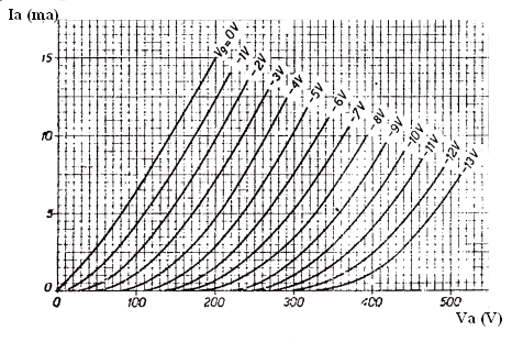
Old valve spec sheets often call the anode voltage Vp. This is the plate voltage and in this case, the anode is called the plate. You will also find anode resistance is sometimes called internal resistance or Ri. This term has fallen out of use as i gets confused with the symbol i used for a changing signal current. The term internal resistance does however describe Ra much better, but if you use the Ri term substitute the term Rint for clarity. The anode current is now measured, Va is changed and the anode current is plotted for different values of anode voltages. The graph is then drawn. This is then repeated for different values of Vg grid voltage and the resultant curves are called anode resistance, plate resistance or Internal resistance.

These two graphs now give you all the data that you need to understand how valves work. They are almost all an amp designer really needs to design an amplifier, apart from heater voltages and maximum values. The manufacturer will have curves for heater voltage values, Ia and other characteristics that only matter to the valve designer. The designer has used these to get the optimum values of the heater current, and various other electrode voltages. Now you have all the data you need but first some simple maths. Try to understand what I am doing in the maths, it will help you. If you can not follow the maths, do not worry, you may not qualify as an amplifier designer, but you can still understand how valves work.
In the next heading I am going to show how from these two graphs we can obtain a formula for the theoretical voltage gain of a valve.
This equation is:
Voltage gain = mutual conductance (gm) x anode resistance (ra)
This page and other technical pages are under continuous construction, as there is still more to be added. If it is not here today it may be tomorrow. Contact us if you want us to add a specific topic or notice any errors.
